 English
 中文简体
中文简体 русский
 日本語
日本語
Home / Newsroom / Industry News / CNC Milling and Turning Explained: A Practical Guide to Processes, Materials, Tolerances, and Choosing the Right Method
Industry News
 Email: cnc88max@dingtalk.com
 Phone: +86-18021988367
Content
CNC milling and CNC turning are the two most widely used subtractive manufacturing processes in precision machining, and together they account for the vast majority of metal and plastic parts produced by CNC machining shops worldwide. Despite often being mentioned in the same breath, they work on fundamentally different principles, produce different part geometries, and use entirely different cutting tool configurations. Understanding the distinction between them is the starting point for making good decisions about how to design and manufacture a part.
In CNC turning, the workpiece rotates at high speed while a stationary cutting tool is fed into it along one or more axes. The spinning workpiece is the primary motion; the tool moves but does not rotate. This arrangement is inherently suited to parts with rotational symmetry — shafts, bushings, pistons, threaded rods, pulleys, and any component whose cross-section is circular or follows a continuous profile around a central axis. The machine performing CNC turning is called a lathe or turning center, and it removes material by peeling continuous chips from the rotating surface, producing excellent surface finishes and very tight dimensional tolerances on diameters and lengths.
In CNC milling, the cutting tool rotates at high speed while the workpiece remains stationary (or moves linearly on the machine table). The rotating multi-flute cutter — an end mill, face mill, drill, or boring tool — is moved along programmed paths to remove material from the workpiece surface. This arrangement is suited to prismatic parts: blocks, plates, brackets, housings, and components with flat faces, pockets, slots, holes, and complex 3D contoured surfaces. The machine performing CNC milling is called a machining center, and it produces parts by removing chips in intermittent, interrupted cuts as each cutter tooth engages and exits the workpiece.
The practical decision between CNC turning and CNC milling for a given part is driven largely by geometry: if the part is rotationally symmetric, turning is faster and more economical; if the part has prismatic features, milling is required. Many real-world components need both — a turned shaft with a milled keyway, for example, or a milled housing with turned and bored bearing bores. This is why CNC turn-mill centers (also called multi-tasking machines or mill-turn lathes) have become increasingly common in modern precision machining facilities, allowing both operations in a single setup on a single machine.
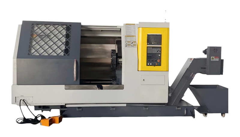
CNC turning is performed on a lathe equipped with a computer numerical control system that drives tool movements with sub-micron positioning repeatability. The process begins with a round bar of stock material — or a forged or cast blank — being clamped in a rotating chuck or collet. The CNC program then commands the turret (which holds multiple cutting tools) to execute the turning operations in sequence.
A typical CNC turning sequence starts with rough turning — removing the bulk of excess material at high feed rates and deep depths of cut (0.5–5 mm depth) to bring the workpiece close to its final dimensions while generating maximum material removal rate (MRR). This is followed by semi-finish and finish turning passes at progressively lower feed rates (0.05–0.2 mm/rev for finishing) and shallower depths of cut (0.1–0.5 mm) to achieve the required diameter tolerance and surface finish. Threading (internal and external), grooving, facing, boring, and parting operations are all performed on the same CNC lathe using dedicated inserts in the turret. Modern CNC turning centers have 8–24 tool positions in the turret, allowing the entire turning sequence to run uninterrupted without manual tool changes.
Cutting speed in turning is expressed as surface feet per minute (SFM) or meters per minute (m/min) — the speed at which the workpiece surface passes the cutting tool edge. For carbide inserts on steel, typical cutting speeds are 200–400 m/min; for aluminum, 500–1,500 m/min; for titanium, 30–80 m/min. Feed rate is expressed as millimeters per revolution (mm/rev) — how far the tool advances per rotation of the workpiece. Lower feed rates produce smoother surfaces (Ra directly related to feed rate and tool nose radius by the formula Ra ≈ f²/8r, where f is feed rate and r is tool nose radius) but take longer. Depth of cut affects material removal rate and the force on the cutting tool — deeper cuts increase productivity but require a stiffer machine and workpiece setup to prevent chatter and deflection.
CNC turning consistently achieves dimensional tolerances of ±0.01–0.025 mm on diameters in standard production conditions on well-maintained turning centers. For bearing fits and precision shaft applications, tolerances of ±0.005 mm (5 microns) are routinely achieved with appropriate tooling, coolant, and measurement feedback. Surface finish on turned surfaces typically ranges from Ra 3.2 µm after rough turning to Ra 0.4–0.8 µm after a fine finishing pass. With superfinishing operations such as hard turning (turning hardened steel at HRC 58–65) using CBN inserts, Ra values below 0.2 µm are achievable, replacing cylindrical grinding in many applications.
CNC milling encompasses a far wider range of operations and machine configurations than turning, reflecting the greater geometric complexity of prismatic parts. The number of axes on the milling machine determines the complexity of shapes that can be produced in a single setup.
The most common configuration is 3-axis CNC milling, where the cutting tool moves simultaneously in X (left-right), Y (front-back), and Z (up-down) directions while the workpiece table remains stationary. This allows machining of all features that can be accessed from above — face milling, pocket milling, slot cutting, hole drilling and boring, and contouring of 3D surfaces with a ball-end mill. The fundamental limitation of 3-axis milling is that undercuts, angled features, and surfaces on the sides of the part require repositioning (re-fixturing) the workpiece, which introduces additional setup time and potential for positioning errors between setups. For parts requiring features on multiple faces, 3-axis machining typically requires 4–6 separate setups, each needing re-zeroing and verification.
4-axis machining adds a rotary axis (the A-axis, rotating around the X-axis) to the 3-axis configuration. The workpiece can be indexed or continuously rotated while cutting, allowing features to be machined on multiple faces and around curved surfaces without re-fixturing. This is particularly valuable for parts like camshafts, spiral flutes on cutting tools, helical gear teeth, and components with radially arranged features. 4-axis milling reduces setup count and maintains better positional relationships between features on different faces compared to multiple 3-axis setups.
5-axis CNC milling adds a second rotary axis (either A+B, A+C, or B+C axis combinations depending on machine configuration), allowing the cutting tool to be tilted and rotated in 3D space relative to the workpiece. This enables machining of highly complex geometries — turbine blades, impellers, orthopedic implants, mold cavities with deep undercuts, and aerospace structural components — in a single setup with the cutting tool approaching the surface from the optimal angle to maintain cutting conditions. True simultaneous 5-axis machining (all 5 axes moving simultaneously during cutting) is required for the most complex geometries, while 3+2 positional 5-axis (where the two rotary axes position the part before cutting with the linear axes) covers a large proportion of complex component requirements at lower programming complexity and machine cost.
General tolerance capability in CNC milling is slightly broader than in turning due to the higher compliance (elastic deflection) of milling cutters compared to turning inserts. Standard production CNC milling achieves ±0.025–0.05 mm general tolerances, with tight-tolerance features such as bored holes, precision datum surfaces, and fitted slot widths achieving ±0.01–0.015 mm with appropriate tooling and measurement feedback. Surface finish on milled faces ranges from Ra 3.2 µm after face milling with a standard carbide insert to Ra 0.8–1.6 µm with fine-pitch finishing passes. Ball-end milled 3D surfaces have characteristic cusps (scallops) between tool paths — the scallop height depends on ball-end radius and step-over distance, and must be controlled by CAM path planning to achieve the required surface quality.
For components that require both turning and milling operations — which describes a very large proportion of precision machined parts — the traditional approach was to run the part on a lathe first, then transfer it to a milling machine for secondary operations. Each transfer between machines introduces setup time, potential for positional error between features, and additional work-in-progress handling. CNC turn-mill centers (also called multitasking machines, mill-turn lathes, or turning-milling centers) solve this by combining a full CNC turning capability with live driven tooling (milling cutters and drills that rotate in the turret) and — on more capable machines — a full milling spindle with B-axis tilt, allowing 5-axis milling operations within the same turning machine.
The productivity advantage of turn-mill machining is substantial for complex rotational parts. A connecting rod, for example, that previously required a turning operation, a transfer, a milling operation for the cap face, another transfer, and a drilling operation for the bolt holes can be completed in a single turn-mill setup — reducing total cycle time by 30–60% and eliminating inter-operation positional errors. Major machine tool manufacturers offering advanced turn-mill centers include Mazak (Integrex series), DMG Mori (NTX series), Nakamura-Tome (NTRX series), and Okuma (MULTUS series), all offering machines with Y-axis off-center milling, live tooling, C-axis contouring, and optionally a full 5-axis milling head.
The programming complexity of turn-mill machining is higher than either standalone turning or milling — the CAM system must manage multiple spindles, coordinate turning and milling operations, handle bar-feeding and part-catching automation, and manage collision avoidance in a crowded machine envelope. CAM software platforms such as Mastercam, hyperMILL, and Siemens NX have dedicated turn-mill modules that address these requirements, generating safe, efficient NC programs for the most complex multi-tasking machines.
Both CNC milling and CNC turning are applicable to a wide range of engineering materials, but each material presents different machinability characteristics that influence tooling selection, cutting parameters, cycle time, and achievable surface quality.
| Material | Machinability | Typical Cutting Speed | Tooling Recommendation | Key Challenges |
| Aluminum 6061/7075 | Excellent | 500–1,500 m/min | Uncoated or ZrN-coated carbide, 3-flute end mills | Built-up edge, chip evacuation in deep pockets |
| Stainless Steel 304/316 | Moderate | 80–200 m/min | PVD TiAlN-coated carbide, positive rake geometry | Work hardening, heat generation, built-up edge |
| Mild Steel (1018, 1045) | Good | 200–400 m/min | Coated carbide inserts/end mills | Long stringy chips, coolant management |
| Titanium (Ti-6Al-4V) | Difficult | 30–80 m/min | Sharp uncoated or AlTiN carbide, high-pressure coolant | Low thermal conductivity, rapid tool wear, springback |
| Inconel 718 | Very Difficult | 15–50 m/min | CBN or ceramic inserts, high-pressure coolant | Extreme heat, rapid tool wear, work hardening |
| Brass (C360) | Excellent | 300–600 m/min | Uncoated carbide, sharp edges | Burr formation, chip control |
| Acetal (Delrin) / Nylon | Good | 200–500 m/min | Sharp uncoated carbide or HSS, dry or air blast | Thermal deformation, dimensional instability, chip welding |
| PEEK / PTFE | Moderate | 150–400 m/min | Sharp carbide, minimal heat generation | Creep under clamping, abrasive wear on tooling (PEEK) |
Design for Manufacturability (DFM) in CNC machining is the practice of making deliberate design decisions that reduce cycle time, tooling cost, setup complexity, and scrap rate without compromising part function. Poorly designed parts can cost 3–10× more to machine than functionally equivalent but better-designed alternatives. These are the most impactful DFM guidelines for CNC milled and turned parts.
Tooling selection has a direct and significant impact on cycle time, surface quality, dimensional accuracy, and cost per part in both CNC milling and turning. The right tool for a given operation balances cutting efficiency, tool life, and the specific demands of the workpiece material and feature geometry.
CNC turning uses indexable carbide inserts held in a tool holder body. Insert selection involves three main decisions: the substrate grade (carbide composition, determining hardness and toughness), the coating (CVD or PVD applied layers of TiN, TiCN, Al₂O₃, or TiAlN that increase wear resistance and reduce friction), and the geometry (insert shape, rake angle, nose radius, and chipbreaker form). For steel turning, ISO P-grade coated carbide inserts (P25 for general roughing, P10 for finishing) are standard. For stainless steel, M-grade inserts with positive rake and polished faces reduce work-hardening tendency. For aluminum, K-grade uncoated or ZrN-coated inserts with high positive rake and a sharp edge minimize built-up edge formation. Nose radius selection affects both surface finish (larger radius = better Ra for a given feed rate) and insert strength (larger radius is stronger but increases radial cutting force and vibration tendency on slender parts).
Solid carbide end mills are the most common milling cutting tools for general CNC machining. Key selection parameters include the number of flutes (2-flute for aluminum and non-ferrous for better chip clearance; 4-flute for steel; 5-7 flute for high-efficiency machining of steel and stainless steel), the helix angle (30–45° for general work; 45°+ for high-speed machining; variable helix for chatter reduction), coating (TiAlN or AlCrN for steel; uncoated or ZrN for aluminum), and reach length (use the shortest possible reach to maximize rigidity). High-efficiency milling (HEM) toolpaths combined with 5–7 flute end mills and optimized chip load calculations have transformed productivity in CNC milling centers over the past decade — MRR improvements of 3–5× over conventional end milling are achievable with the right tool and CAM strategy combination.
Cutting fluid management is often underestimated as a factor in CNC milling and turning performance. For steel and stainless steel, flood coolant (water-soluble oil at 5–10% concentration) is standard — it controls cutting temperature, flushes chips from the cutting zone, and extends tool life significantly. For titanium and Inconel, high-pressure coolant directed precisely at the cutting edge (40–150 bar through-tool or directed nozzles) is essential because these materials have low thermal conductivity and heat concentrates at the tool tip. For aluminum, flood coolant is beneficial but not critical — the material machines well dry or with minimum quantity lubrication (MQL, a fine oil mist applied at 10–50 ml/hr). For plastics and composites, dry machining or compressed air blast is preferred because coolant can cause swelling, dimensional instability, or contamination of the workpiece.
As-machined surface finish is often sufficient for functional mechanical components, but many applications require post-processing for improved aesthetics, corrosion resistance, wear resistance, or dimensional refinement. Understanding what is achievable — and what it costs — is important for both designers and buyers of CNC machined parts.
Choosing the right CNC machining partner for milling and turning work has a direct impact on part quality, delivery reliability, and total cost of procurement. These are the key capability and quality factors to assess when qualifying a CNC machining supplier, whether for prototype, low-volume, or production quantities.
A capable CNC machining supplier should be able to demonstrate that their machine tool inventory matches the complexity and volume of your parts. For precision parts requiring tight tolerances, ask about machine tool age, last calibration date, and positioning accuracy specifications (typically ISO 230-2 certified positioning accuracy of 5–10 µm and repeatability of 2–5 µm for quality precision machines). Shops offering 5-axis milling and turn-mill capability can handle more complex geometry in fewer setups — which generally means better geometric accuracy between features and lower setup-related cost per part.
ISO 9001 certification is the baseline quality management standard for CNC machining suppliers serving industrial customers — it confirms that the shop has documented processes for order control, material traceability, process control, non-conformance management, and corrective action. For aerospace (AS9100), medical (ISO 13485), or automotive (IATF 16949) parts, the relevant sector-specific quality management standard should be certified and current. Inspection capability is equally important: the shop should have calibrated coordinate measuring machines (CMMs), calibrated micrometers and bore gauges, surface roughness testers, and — for thread inspection — calibrated thread gauges and optical comparators. Ask to see a sample First Article Inspection (FAI) report from a similar precision part to assess the thoroughness of their dimensional reporting.
For regulated or safety-critical applications, material traceability from raw stock to finished part is a non-negotiable requirement. A capable supplier should be able to provide EN 10204 3.1 mill certificates (certified by the material manufacturer's inspection representative) for all metallic raw materials, cross-referenced to the specific parts shipped using heat numbers and lot numbers. For medical and aerospace applications, full material traceability to the original ingot heat is required and must be maintained in document control records for the specified retention period (typically 10 years minimum for aerospace parts).
Beyond technical capability, the practical reliability of a CNC turning and milling supplier is determined by their capacity management, scheduling transparency, and communication quality. Request references from existing customers for similar volume and complexity work. Ask about their standard lead times for prototype (typically 5–15 business days for complex parts), low-volume production (3–6 weeks), and production repeat orders (1–3 weeks with existing programs and tooling). Evaluate how promptly and clearly they respond to RFQs — a supplier who takes 2 weeks to quote a simple turned part and provides minimal technical feedback will likely exhibit the same communication pattern when problems arise during production.

Copyright © Xuancheng Huzheng Machinery Trading Co., Ltd. Rights Reserved.