 English
 中文简体
中文简体 русский
 日本語
日本語
Home / Newsroom / Industry News / Dual-Spindle Turning and Milling Machine: Types, Benefits & Buying Guide
Industry News
 Email: cnc88max@dingtalk.com
 Phone: +86-18021988367
A dual-spindle turning and milling machine takes everything that makes a standard CNC lathe useful and then doubles the output, adds full milling capability, and finishes parts completely in a single setup. Instead of moving a workpiece from a turning center to a machining center and back again — accumulating setup errors, handling time, and scheduling delays at every transfer — a dual-spindle mill-turn center handles the entire machining sequence from raw bar stock to finished part without the operator touching it between operations. This guide covers how these machines are built, the different configurations available, which applications justify the investment, and what to evaluate when choosing between options.
Content
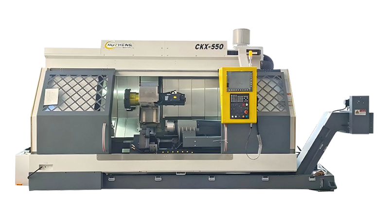
A dual-spindle turning and milling machine — also called a twin-spindle mill-turn center, dual-spindle multitasking lathe, or turn-mill machining center — integrates two independent workholding spindles and live-tool milling capability within a single machine enclosure. The two spindles are the defining feature. The main spindle holds and rotates the workpiece for the initial turning operations, exactly as a conventional CNC lathe would. The sub-spindle (also called the counter-spindle or secondary spindle) is positioned coaxially opposite the main spindle — it can advance along the Z-axis to grip the machined front face of the part, accept a synchronized transfer from the main spindle, and then present the opposite (back) face of the part to the cutting tools without any manual reclamping or repositioning.
The live tooling system is built into the turret — the tool-holding drum that indexes to present different cutting tools to the workpiece. Unlike a standard turning turret, which holds only static turning tools, a live-tool turret mounts rotating tools such as end mills, drills, taps, and reamers that are driven by an independent motor built into the turret. These live tools are active when the main or sub-spindle is locked in a specific angular position via C-axis control, allowing the machine to mill flats, drill off-center holes, machine cross-holes, cut slots, and tap threads — operations that would require a separate machining center on any conventional turning center.
The most capable dual-spindle turn-mill machines add a Y-axis to the turret — linear motion perpendicular to both the spindle centerline and the tool approach direction. This is what allows true milling operations with straight walls, flat pockets, and off-center features that are geometrically impossible to produce with only X- and Z-axis motion. The combination of two spindles, live tooling, C-axis control, and Y-axis motion gives a dual-spindle turning and milling machine the ability to complete complex parts in a single chucking, from raw material to finished dimensions, on all six faces.
Dual-spindle turning and milling machines exist across a wide capability spectrum. The appropriate configuration depends on part complexity, production volume, and what operations need to be completed in a single setup.
At the entry level of the dual-spindle category are twin-spindle turning centers with live tooling but without a Y-axis. These machines have opposing main and sub-spindles, a live-tool turret, and C-axis control on both spindles. They handle the full front-to-back turning and drilling sequence on parts that require holes and features on the spindle centerline, but they cannot produce off-center milled features or pockets with straight walls. This configuration is common in automotive and hydraulics production where parts require complete OD and ID turning plus centerline drilling and tapping on both ends — but not complex milling geometry.
Adding a Y-axis to the turret unlocks the full milling capability of the machine. With Y-axis travel of typically ±40 to ±60 mm, the machine can produce features at any offset from the spindle centerline — keyways, flats, off-center bores, pockets, slots, and contoured surfaces. The Y-axis also enables true eccentric turning using interpolated C- and Y-axis motion for cam profiles and non-round features. Machines in this category cover the majority of complex aerospace, medical, and precision engineering parts that previously required both a turning center and a vertical or horizontal machining center to complete. The Haas DS-30Y, Hurco TMXMYS, and YCM B8-SY are representative examples of this class.
The highest-capability dual-spindle turning and milling machines add a second turret — typically positioned below the spindle centerline — and provide independent Y-axis control on both upper and lower turrets. This means two separate tool stations can cut simultaneously on a single workpiece: the upper turret can rough-turn the OD while the lower turret bores the ID, cutting total cycle time roughly in half for bore-heavy parts. When the sub-spindle accepts the part after front-face completion, both turrets are again available — one for back-working in the sub-spindle, one simultaneously cutting a new part in the main spindle. Doosan's PUMA TT2100SYY and Mazak's INTEGREX series represent this class, which is standard in high-production aerospace, defense, and medical device manufacturing where cycle time and machine utilization are both critical.
The most capable category adds a swiveling B-axis milling head — a machining center-style spindle that can tilt through a range of typically ±90° — to the dual-spindle platform. The B-axis allows 5-axis simultaneous interpolation on complex contoured features like turbine blade profiles, compound-angle bores, and tapered features at arbitrary angles. Machines with a true B-axis milling head, such as those in the Mazak INTEGREX e series or DMG Mori NTX series, are essentially full machining centers with turning capability added, rather than the reverse. Tool capacities reach 80 to 120 tool positions in automatic tool changers (ATC), and axis counts reach 9 or more on the most complex configurations.
Understanding the axis configuration of a dual-spindle turning and milling machine is the starting point for evaluating whether a specific machine can complete a specific part. The table below maps each axis to its physical motion and the machining capability it unlocks.
| Axis | Motion | Machining Capability Enabled |
|---|---|---|
| X-axis | Radial (cross-slide) movement of tool toward/away from spindle | OD/ID turning diameter control; facing cuts |
| Z-axis | Axial movement of tool or spindle along spindle centerline | Length control; taper turning; thread cutting |
| C-axis (main & sub) | Rotary positioning/interpolation of spindle | Angular positioning for live tool drilling; contour milling with Y; polygon turning |
| Y-axis | Linear motion perpendicular to X and Z | Off-center milling; pockets with straight walls; keyways; eccentric boring |
| B-axis | Rotary swivel of milling head about Y-axis | 5-axis simultaneous machining; compound-angle bores; turbine/impeller features |
| Sub-spindle Z (W-axis) | Independent axial movement of sub-spindle | Synchronized part transfer; back-face machining; sub-spindle parting |
The business case for a dual-spindle turning and milling machine rests on several compounding productivity advantages that accumulate across every part cycle.
In a conventional machining workflow, a rotationally symmetric part requiring front-face turning, back-face turning, and milling operations requires a minimum of three separate setups across two or three different machines. Each transfer between machines introduces repositioning error as the part is re-clamped in a new fixture or chuck. These accumulated errors are why tight-tolerance parts with features on multiple faces are difficult to hold on conventional multi-machine routings — every rechucking adds its own runout and positional error. A dual-spindle turning and milling machine eliminates every intermediate setup: the part is chucked once in the main spindle, machined completely on the front face, transferred automatically to the sub-spindle with a programmed synchronized transfer cycle, and machined completely on the back face — all in one continuous program. The result is part-to-part repeatability that matched machining center tolerances cannot consistently achieve.
Twin-turret dual-spindle machines allow two cutting operations to proceed simultaneously — one on the main spindle and one on the sub-spindle — in what is called overlapping operation or balance cutting. While the sub-spindle completes the back-face operations on part N, the main spindle begins front-face operations on part N+1, which was bar-fed automatically during the sub-spindle cycle. This overlap eliminates the dead time between parts that is unavoidable on single-spindle machines. On high-volume production parts — automotive bearing housings, hydraulic valve bodies, pump impellers — overlapping operation routinely reduces effective cycle time per part by 30 to 50 percent compared to sequential single-spindle processing.
When parts leave the dual-spindle turning and milling machine complete — all turning, milling, drilling, tapping, and finishing operations done — work-in-process inventory drops dramatically. Parts are not queued between operations waiting for machine availability, setup time, or operator attention. Floor space occupied by in-process staging racks, inter-machine conveyors, and the multiple machines being replaced is recovered. Lead times from raw material to finished part compress from days (across multiple machine queues) to hours (a single machine cycle). For high-mix, lower-volume shops, this means a wider range of part numbers can be run economically on a single machine platform with short changeover times.
CNC accuracy on a dual-spindle turning and milling machine compounds across all operations because the part never leaves the controlled environment of the machine's coordinate system between operations. Features machined on the front face are referenced to the same datum as features machined on the back face — there is no setup-to-setup datum shift as there would be on two separate machines. On precision shafts with coaxial front and back features, this translates directly to tighter total runout and concentricity tolerances. Modern dual-spindle mill-turn machines with linear glass scale feedback and thermal compensation achieve positioning repeatability of ±0.002 mm or better across all axes, enabling parts to be machined to ground-tolerance equivalents without a secondary grinding operation on many features.
Dual-spindle turning and milling machines deliver the strongest productivity and quality returns on part families with specific characteristics: rotational symmetry, features on both ends, milled or drilled off-center features, and medium-to-high production volumes. These characteristics concentrate in a handful of industries.
Dual-spindle turning and milling machines range from mid-range production lathes starting around $150,000 to full multi-axis mill-turn centers exceeding $1,000,000 for the most capable configurations. Selecting the right machine requires matching specifications to the actual requirements of the parts being produced — not buying capability that will never be used, and not under-specifying a machine that will limit production from day one.
Main spindle power for dual-spindle turning and milling machines typically ranges from 15 HP (11 kW) on compact bar-work machines to 45 HP (33 kW) or more on large-diameter production machines. Sub-spindle power is generally 50 to 70 percent of main spindle power. Speed range matters for both turning and live tool operations — main spindle speeds of 4,000 to 6,000 RPM cover the majority of turned materials; live tool motor speeds of 3,000 to 6,000 RPM accommodate end mills and drills across the typical size range for turned parts. For titanium and other hard-to-machine alloys, verify that the machine provides adequate low-speed torque for heavy roughing cuts, not just high RPM for finishing.
Bar capacity — the maximum bar stock diameter that passes through the main spindle — directly limits what parts can be bar-fed on the machine. Common bar capacities range from 42 mm (1.65 inches) for compact precision machines up to 100 mm or larger for heavy-duty production machines. Sub-spindle through-hole diameter is typically smaller than the main spindle — verify it accommodates the parts being transferred if through-boring on the sub-spindle is required. Chuck sizes (6-inch, 8-inch, 10-inch) determine the maximum grip diameter for chuck-loaded parts that exceed bar capacity.
Y-axis travel determines the maximum offset from centerline at which milling operations can be performed. For most turned-part milling features — cross-holes, keyways, flats — ±40 to ±50 mm is adequate. For larger parts with features further from the centerline, or for deep pockets, verify that the Y-axis range covers the actual feature locations on the parts being considered. Some machines offer Y-axis only on the main turret; verify whether sub-spindle operations also have Y-axis access if back-face milling at offset is required.
Turret capacity — the number of indexed tool positions available — determines how complex a part can be machined without a tool change or manual intervention. Standard 12-station turrets handle typical turned-and-drilled parts; 24-station BMT turrets or machines with dual turrets accommodate complex parts requiring many distinct tools. Total tool count including live tool positions matters for high-mix production — a machine with 38 total tool positions (including a secondary sub-turret) can hold a full family of tools for multiple part numbers simultaneously, enabling rapid changeover between jobs without full re-tooling.
The quality of the synchronized spindle transfer — the automatic handoff of the part from the main spindle to the sub-spindle — directly affects the accuracy of the relationship between front-face and back-face features. Synchronized transfer requires both spindles to run at exactly the same speed and phase simultaneously, with the sub-spindle advancing to grip the part while it rotates. A well-implemented transfer adds essentially no positioning error between faces; a poorly implemented one introduces axial and angular offset that degrades part quality. Ask for demonstrated transfer accuracy data (axial runout and angular repeatability after transfer) when evaluating specific machines for tight-tolerance applications.
The CNC control handles all axis interpolation, spindle synchronization, live tool coordination, and part program management. Fanuc, Siemens, Mitsubishi, and Mazatrol are the dominant control platforms in dual-spindle turning and milling machines. Beyond brand preference, evaluate specific control features: conversational programming capability for rapid job setup, background editing so programs can be modified while the machine runs, dual-path (dual-channel) control architecture for simultaneous independent control of main and sub-spindle operations, and sub-spindle mirroring functions that automatically flip and transfer programs from main to sub-spindle geometry. Hurco's conversational control and Mazak's Mazatrol programming are consistently cited as differentiators for shops that need rapid program creation for high-mix production.
The decision between investing in a dual-spindle turning and milling machine versus maintaining separate turning and milling equipment comes down to part mix, volume, accuracy requirements, and total cost of ownership over the machine's life.
| Factor | Dual-Spindle Mill-Turn Center | Separate Turning + Milling Machines |
|---|---|---|
| Setup time per part | One setup for all operations | Multiple setups across multiple machines |
| Positional accuracy between faces | Excellent — single datum, no rechucking error | Variable — each rechucking introduces error |
| Cycle time for complex parts | Shorter — overlap of main/sub operations | Longer — sequential, plus queue and transfer time |
| Floor space | One machine footprint | Two to four machines plus staging areas |
| Capital cost | Higher upfront (one machine) | Lower per machine; higher total for equivalent capability |
| Operator labor per part | Lower — fewer setups, less handling | Higher — multiple setups and machine transfers |
| Best for | Complex parts, medium-high volume, tight tolerances | Very simple parts, large-diameter turning only, ultra-high volume single-op work |
| Flexibility for new parts | High — one machine handles wide variety | Lower — new parts may need routing adjustments across machines |
For most shops producing parts with features on more than one face or requiring both turning and milling, the total cost of ownership comparison typically favors the dual-spindle mill-turn center at medium and above production volumes — especially when operator labor, floor space, and work-in-process carrying costs are included in the analysis alongside the machine purchase price.
Getting the most out of a dual-spindle turning and milling machine requires programming approaches that are more sophisticated than conventional CNC turning, and setup practices that account for the machine's multi-operation capability.

Copyright © Xuancheng Huzheng Machinery Trading Co., Ltd. Rights Reserved.