 English
 中文简体
中文简体 русский
 日本語
日本語
Home / Newsroom / Industry News / Multi-Process Composite Machining: Capabilities, Equipment & Application Guide
Industry News
 Email: cnc88max@dingtalk.com
 Phone: +86-18021988367
Content
Multi-process composite machining refers to the integration of two or more distinct machining operations — such as turning, milling, drilling, grinding, gear cutting, or even additive manufacturing — into a single machine platform that completes a part in one setup or a minimal number of setups. The term "composite" in this context does not refer to composite materials; it refers to the composite nature of the process itself — multiple manufacturing operations combined into a unified, continuous workflow on one piece of equipment.
Traditional manufacturing routes for complex parts require sequential operations on separate machines: a lathe for turning, a machining center for milling, a surface grinder for finishing, and potentially additional dedicated equipment for features like gear teeth, threads, or deep holes. Each machine handoff involves workpiece re-clamping, re-fixturing, and re-referencing — each of which introduces positioning error, adds handling time, and creates opportunity for damage to the part. In high-precision manufacturing, the cumulative error from multiple setups can consume a significant fraction of the available tolerance budget before any cutting even begins.
Multi-process composite machining eliminates or dramatically reduces these inter-process handoffs. A composite machining center equipped with turning spindles, live milling tools, B-axis or Y-axis capability, and integrated measurement probing can take a raw billet or casting from the first roughing cut to a finished, dimensionally verified part without the workpiece ever leaving the machine envelope. This is not simply a convenience — it fundamentally changes the achievable accuracy, cycle time, and production economics for complex precision components.
The specific process combinations available in composite machining equipment vary by machine configuration, but several fundamental combinations have become standard in the industry. Understanding what each combination enables — and what it requires from the machine architecture — is the starting point for evaluating whether composite machining is the right solution for a given part family.
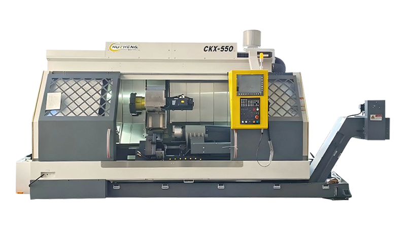
Turn-mill is the most widely adopted form of multi-process composite machining. A turn-mill center combines a primary turning spindle — which rotates the workpiece for conventional lathe operations — with a milling spindle or live tooling turret that can perform rotary cutting operations on the stationary or slow-rotating workpiece. This combination allows a single machine to produce rotationally symmetric features through turning while also generating prismatic features — flats, slots, cross-holes, helical grooves, and milled pockets — that would otherwise require a separate machining center. Modern turn-mill centers add Y-axis capability (off-centerline milling), B-axis tilt (angled hole drilling and milling), and often a sub-spindle that grips the part from the opposite end to allow backworking operations without manual re-chucking. This configuration is particularly powerful for shaft-type components, hydraulic manifolds, and aerospace structural parts that combine rotational and prismatic features.
Mill-turn centers are architecturally similar to turn-mill machines but are oriented primarily as machining centers with an added turning capability. The primary spindle clamps the workpiece for 5-axis milling, and a turning function is added through a secondary spindle or by rotating the workpiece against stationary turning tools. Mill-turn is the preferred configuration for parts that are primarily prismatic with some rotational features — components where the majority of material removal is milling but where turning a diameter, boring a circular pocket, or producing a turned surface is also required. The distinction between turn-mill and mill-turn is architectural rather than absolute, and many manufacturers use the terms interchangeably for machines with balanced turning and milling capability.
Integrating grinding into a composite machining center extends the process chain from rough and semi-finish machining through to hard finishing — all in a single setup. This is particularly significant for hardened steel components where turning and milling must be performed before hardening, after which only grinding can achieve the required surface finish and dimensional accuracy. A composite machining center with integrated cylindrical or internal grinding capability eliminates the second-setup accuracy loss that occurs when a turned and milled part is transferred to a separate grinding machine after heat treatment. Hard turning as an alternative to grinding is well established for some applications, but for the tightest tolerances — below IT5 grade and Ra below 0.4 µm — integrated grinding within the composite machining cell remains the most reliable path to consistent results.
The newest frontier in multi-process composite machining is the integration of additive manufacturing — typically directed energy deposition (DED) using a laser powder nozzle — with conventional subtractive machining in the same machine envelope. An additive-subtractive composite machining center can build up material in specific locations through laser cladding or DED, then immediately machine the deposited material to finished dimensions without removing the workpiece. This capability enables repair of worn or damaged high-value components — rebuilding worn bearing journals on aerospace shafts, restoring turbine blade tips — as well as the production of near-net-shape parts with complex internal features that cannot be produced by subtractive machining alone. Additive-subtractive composite machines currently represent a small fraction of the installed base but are the fastest-growing segment of the composite machining market.
The physical architecture of a composite machining center — the arrangement of axes, spindles, turrets, and tool changers — determines which process combinations are possible and how efficiently they can be executed. Several machine architectural configurations have become established as the primary platforms for multi-process composite machining.
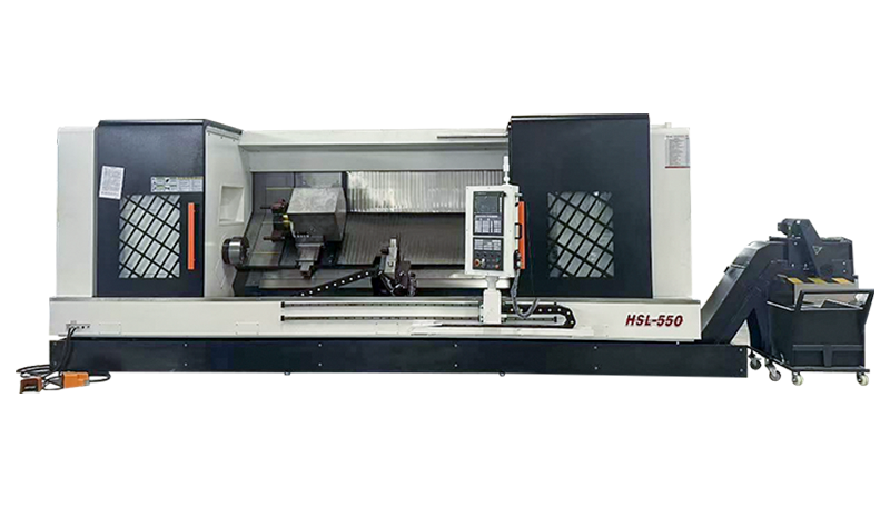
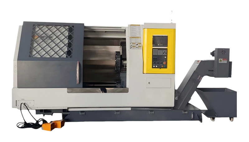
The slant-bed lathe with a driven tool turret, Y-axis, and sub-spindle is the workhorse platform of production-oriented turn-mill composite machining. The slant bed provides chip clearance and structural rigidity; the Y-axis enables off-center milling; the sub-spindle grips the part for backworking after the main spindle operations are complete. This architecture is highly mature, widely available from multiple manufacturers, and optimized for shaft, fitting, and connector components produced at medium-to-high volume. The limitation is that the turret-based tool system restricts the milling spindle power and speed available — driven tool turrets typically provide 5 to 15 kW of milling power compared to 20 to 50 kW on a dedicated machining center spindle — making them less suitable for heavy milling operations on large or hard workpieces.
Higher-capability composite machining centers replace the turret-mounted driven tools with a dedicated milling spindle head mounted on a B-axis that tilts through a defined angular range — typically ±90° to ±120°. This architecture delivers full machining center milling power and speed alongside turning capability, enabling heavy face milling, deep pocket milling, and 5-axis simultaneous contouring in addition to all standard turning operations. The B-axis tilt allows angled features — compound angle holes, inclined surfaces, undercuts — to be produced without repositioning the workpiece. Machines in this category — such as the Mazak Integrex series, DMG Mori NTX series, and Okuma MULTUS series — represent the high-capability end of turn-mill composite machining and are the preferred platforms for aerospace, energy, and medical device component production.
Twin-spindle, twin-turret composite machining centers mount two facing spindles and two independent turrets in the same machine, enabling simultaneous machining of both ends of a part or parallel processing of two separate parts at once. Cycle time on balanced twin-spindle operations can approach half that of sequential single-spindle machining. This architecture is particularly effective for high-volume production of short shaft and chuck-type components where the part geometry allows meaningful simultaneous operations at both ends — automotive transmission components, hydraulic fittings, and similar parts produced in the thousands per shift.
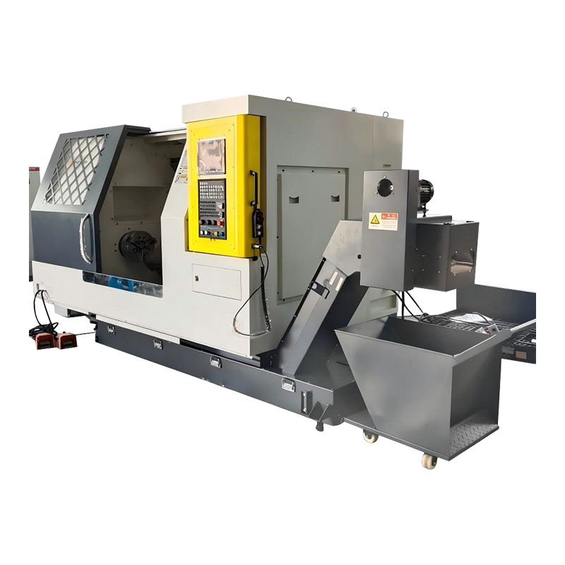
One of the most compelling quantitative arguments for multi-process composite machining is the improvement in achievable part accuracy that results from eliminating re-setup errors. Understanding the magnitude of this improvement — and where it does and doesn't apply — is essential for evaluating whether composite machining is justified for a specific part.
| Accuracy Factor | Multi-Setup Conventional Route | Composite Machining (Single Setup) |
| Positional re-setup error | ±0.02 – ±0.1 mm per setup | Eliminated (single datum) |
| Concentricity / coaxiality | 0.02 – 0.05 mm typical | 0.005 – 0.015 mm achievable |
| Perpendicularity of milled to turned features | 0.02 – 0.08 mm | 0.005 – 0.02 mm |
| Total lead time per part | Multiple queue waits between machines | Single machine cycle time |
| WIP inventory | High — parts queue at each machine | Minimal — parts flow continuously |
| Handling damage risk | Multiple transfer and re-fixturing events | Minimized — one load/unload |
The accuracy improvement from single-setup composite machining is most significant for geometric tolerances that relate features machined at different stages of the process — concentricity between a turned bore and a milled bolt circle, perpendicularity between a turned shaft diameter and a milled face, or position of cross-drilled holes relative to a turned centerline. These inter-feature relationships can only be held to their full tolerance potential when all features are referenced to the same datum in the same setup. For features that are entirely independent — a milled flat on one face and a turned diameter on another face with no specified relationship between them — the accuracy advantage of composite machining is less pronounced, though cycle time and WIP reduction benefits still apply.
The expanded capability of multi-process composite machining centers comes with a corresponding increase in programming complexity. A part that required separate programs for a lathe, a vertical machining center, and a cylindrical grinder now requires a single integrated program that coordinates all operations — including synchronization of simultaneous operations, axis collision avoidance, tool change sequencing, and in-process measurement cycles. This complexity requires both capable CAM software and skilled programmers who understand both turning and milling programming methodologies.
Not all CAM software handles composite machining equally well. Programs written in basic CAM systems designed for either turning or milling alone are inadequate for multi-process machines — they cannot simulate the full machine kinematics, coordinate multi-spindle synchronization, or verify collision avoidance across the complete machine envelope. Production-grade composite machining programming requires CAM systems with native multi-tasking modules — Mastercam Mill-Turn, Siemens NX CAM, Hypermill Turn Mill, or dedicated modules within the machine manufacturer's own programming environment. These systems import the complete machine kinematic model and simulate the full machining cycle, flagging collisions between tool holders, chuck jaws, tailstock, and workpiece before the program runs on the actual machine. Machine simulation is not optional for composite machining — the consequences of a collision in a machine worth €500,000 or more are severe enough to make virtual verification a mandatory step in any responsible production workflow.
Twin-spindle and twin-turret composite machining centers require synchronization programming — the explicit coordination of operations on both spindles and both turrets to run simultaneously where possible without mutual interference. Synchronization is typically managed through WAIT commands or synchronization codes in the CNC program that hold one channel until the other has completed a defined operation before both proceed. Optimizing the synchronization to minimize idle time on either spindle — balancing the work between main spindle and sub-spindle so both are cutting for the maximum proportion of the cycle — is what delivers the theoretical cycle time reduction of twin-spindle machines. Poorly synchronized programs can eliminate most of the cycle time advantage by leaving one spindle idle while waiting for the other, effectively running the machine as a sequential rather than parallel processor.
Composite machining centers are increasingly equipped with on-machine probing systems — touch-trigger or scanning probes mounted in the tool changer — that measure workpiece features during the machining cycle and feed back dimensional data to the CNC for automatic tool offset correction. This closed-loop capability is particularly valuable in composite machining because the single-setup nature of the process means there is no opportunity for inter-operation inspection and correction. An error that develops during turning — a diameter growing as the insert wears — can affect the position of subsequently milled features if it is not detected and corrected within the same cycle. Programming the measurement cycles, defining correction logic, and setting tolerance limits for automatic versus alarm-flagged corrections is an integral part of composite machining process development, not an afterthought.
Multi-process composite machining delivers the greatest benefit for parts that combine multiple feature types, require tight inter-feature tolerances, are produced in low-to-medium volumes where setup amortization is significant, or are made from expensive or difficult-to-machine materials where minimizing handling and fixturing risk reduces scrap rate.
The capital cost of a composite machining center — typically two to five times the cost of a comparable single-process machine — means the investment decision requires careful analysis of where and how that cost is recovered through production benefits. Not every part and not every operation justifies composite machining, and making the investment without a clear economic case creates financial exposure that undermines the technology's genuine advantages.

Copyright © Xuancheng Huzheng Machinery Trading Co., Ltd. Rights Reserved.