 English
 中文简体
中文简体 русский
 日本語
日本語
Home / Newsroom / Industry News / CNC Turning and Milling Centers: What They Are, and How to Choose One
Industry News
 Email: cnc88max@dingtalk.com
 Phone: +86-18021988367
Content
A CNC turning and milling center — also called a turn-mill center, multi-tasking machine, or CNC lathe with live tooling — is a machine tool that performs both rotational turning operations and rotary milling, drilling, and tapping operations in a single setup without removing the workpiece from the spindle. Conventional machining separates these operations across dedicated lathes and machining centers, requiring the operator to manually transfer the part between machines, re-fixture it, and re-datum it for each successive operation. Every transfer introduces positional error that accumulates through the machining sequence, requiring generous tolerances or post-process inspection to manage. A turning and milling center eliminates all of these intermediate setups by completing the entire machining sequence — or the vast majority of it — in a single clamping.
The machine integrates a CNC lathe spindle with a C-axis (rotary indexing capability about the spindle axis) or full contouring control, combined with a driven tool turret or secondary milling spindle that holds and rotates cutting tools independently of the main workpiece spindle. This driven tooling capability is what distinguishes a turning and milling center from a standard CNC lathe — the tools themselves can spin, enabling off-center drilling, cross-drilling, flat milling, slot cutting, and thread milling on cylindrical or complex prismatic features without repositioning the part. High-end turn-mill centers add Y-axis travel perpendicular to both the X and Z axes, enabling fully offset milling operations on features that do not lie on the part's centerline — a capability required for machining eccentric bores, key slots, flats, and compound-angle features that would otherwise be impossible to complete on a lathe-type machine.
The business case for CNC turning and milling centers is compelling for any shop producing complex rotational parts in medium-to-high volume. Eliminating inter-machine transfers reduces total cycle time, cuts work-in-process inventory, removes the need for intermediate gauging stations, and allows a single machine operator to supervise the complete production of a part. In high-mix environments where setup time is a significant portion of total cost per part, reducing from three or four machine setups to one produces immediate and measurable productivity gains.
CNC turning and milling centers are not a single machine type but a family of configurations, each optimized for a different balance of complexity, workpiece size, production volume, and budget. Understanding how these configurations differ is essential to specifying the right machine for a given production requirement — a machine that is over-featured for the work generates unnecessary capital cost and complexity, while an under-specified machine forces compromises that defeat the purpose of multi-tasking machining.
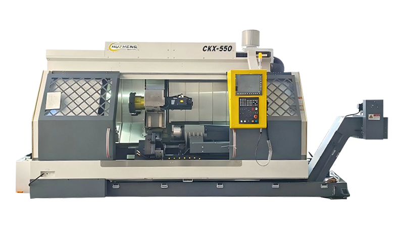
The entry-level configuration for turn-mill machining is a CNC lathe with a driven tool turret and C-axis spindle positioning. The turret holds a mix of static turning tools and driven milling/drilling heads powered by an internal motor in the turret body. The main spindle indexes to any angular position under C-axis CNC control, allowing the driven tools to perform axial and radial drilling, milling, and tapping at any clocked position around the part's circumference. This configuration covers the majority of turn-mill applications for bar-fed shaft and flange components: cross-holes, axial threaded ports, hex or square driving features, and simple flats. The limitation is the absence of a Y-axis — all milling operations must be performed at the part centerline or at positions achievable through C-axis rotation combined with X-axis tool positioning, which restricts off-center features to those that can be produced by helical interpolation in the C-X plane.
Adding a true Y-axis — typically ±50 to ±100mm of travel perpendicular to the X-Z plane — to a driven-tool turret machine enables off-center milling, eccentric bore drilling, keyway cutting, and any feature that does not lie on the part's rotational axis. The Y-axis is the capability that distinguishes a true turning and milling center from a lathe with incidental milling capability. Machines in this category also commonly include a secondary sub-spindle that picks up the part after front-end machining and presents the back face for simultaneous or sequential machining — enabling complete OP10/OP20 machining in a single machine cycle. This sub-spindle configuration is standard for high-volume production of shaft and coupling components where both ends require machining.
Swiss-type turning and milling centers use a sliding headstock and guide bushing arrangement where the workpiece is supported very close to the cutting zone by a fixed guide bushing, with the material feeding axially through the bushing as it is machined. This support arrangement virtually eliminates workpiece deflection during cutting, enabling precise turning of very slender parts — typically bar stock from 1mm to 38mm diameter — at length-to-diameter ratios of 20:1 or higher that would cause deflection and chatter on a conventional lathe. Swiss-type turn-mill centers combine this precision turning capability with multiple driven tool stations for milling, drilling, and back-working, making them the standard machine type for high-volume production of small precision components: medical screws and implants, watch components, dental instruments, hydraulic valve bodies, and electronics connector pins.
For large workpieces — heavy shafts, large flanges, turbine components, and wind energy parts — horizontal turning centers with integrated B-axis milling spindles are used. The B-axis allows the milling spindle to tilt to any angle in the vertical plane, enabling 5-axis simultaneous machining of complex surfaces, angled bores, and compound features on large, heavy components that would be impossible to reposition safely between operations. Vertical turning centers (VTCs) with integrated milling capability handle large-diameter disk and ring components — brake discs, gear blanks, pump impellers — using a vertical spindle orientation that allows gravity to assist workpiece clamping and makes loading large parts with a crane or robot straightforward.
Comparing CNC turning and milling centers across manufacturers requires evaluating a comprehensive set of specifications that together define the machine's capability envelope for a given family of workpieces. Focusing on headline specifications like spindle speed while overlooking equally important parameters like turret index time, Y-axis travel, and bar capacity produces poor purchasing decisions that constrain production capability for the machine's entire service life.
| Specification | Typical Range | Why It Matters |
|---|---|---|
| Main Spindle Speed | 3,000–10,000 RPM | Determines turning speed for small-diameter finishing cuts and surface speed for hard materials |
| Main Spindle Power (kW) | 11–55 kW | Defines metal removal rate capability in roughing and heavy interrupted cuts |
| Driven Tool Speed | 4,000–12,000 RPM | Sets maximum surface speed for milling and drilling operations with driven tools |
| Y-Axis Travel | ±40 to ±100 mm | Defines off-centerline milling reach for eccentric features and keyways |
| Bar Capacity (diameter) | 25–102 mm | Maximum bar stock diameter that feeds through the spindle for automatic bar feeding |
| Turret Stations | 8–24 stations | Limits tool variety per program; more stations reduce tool change frequency in complex programs |
| Sub-Spindle (Yes/No) | Optional | Enables complete OP10/OP20 machining without part removal |
| Maximum Turning Diameter | 150–800 mm | Swing over the bed defines the maximum OD workpiece the machine can accommodate |
The driven tool power and speed specification deserves particular attention because it is frequently understated in machine specifications relative to the main spindle. A turning center with a 22kW main spindle but only 3.7kW driven tool motors will produce excellent turning results but will be constrained to light milling cuts and small-diameter drilling — unable to take advantage of modern solid carbide end mills and drills at recommended cutting parameters. For shops where milling operations represent a significant portion of the programmed cycle time, driven tool power should be evaluated against the specific milling operations planned, not just compared against competing machine specifications.
Not every part benefits equally from turn-mill machining. The greatest advantages accrue to parts that are primarily rotational in character — turned outside diameters, bored internal features, threaded surfaces — but also carry secondary prismatic features that would normally require a second machine setup on a vertical or horizontal machining center. Identifying whether a part family fits this profile is the first step in building the business case for turn-mill investment.
Drive shafts, pump shafts, and spindle shafts that require turned diameters, threads, and ground journals combined with cross-drilled holes, transverse flats, key slots, or Woodruff keyways are ideal turn-mill candidates. On a conventional lathe, the turning sequence is completed first, then the shaft is transferred to a milling machine or drill press for the secondary features — a process involving multiple fixtures, potential for datum shift, and significant handling time. On a turning and milling center, all features are completed in one clamping with a single datum reference, producing inherently better positional accuracy between the turning and milling features and eliminating all inter-machine transfer time.
Hydraulic manifolds, valve bodies, pump housings, and flanged connectors combine turned bores and external diameters with bolt hole patterns, ported passages, and sealing grooves that are distributed around the part's circumference. The C-axis indexing of a turn-mill center positions these distributed features precisely by rotating the main spindle to the required angular position before each driven-tool operation — eliminating the rotary table or indexer that would be required to achieve the same positioning on a machining center. The result is faster cycle time, better angular position accuracy, and fewer fixtures in the workflow.
Bone screws, dental implants, surgical instrument components, and aerospace fasteners and fittings are produced in high volumes from difficult materials — titanium alloys, cobalt-chrome, Inconel, and stainless steel — with tight tolerances on both turned and milled features. In these sectors, the cost of scrap, rework, and inspection failure is disproportionately high relative to raw material and cutting tool costs. Reducing the number of setups directly reduces the number of opportunities for positioning error, handling damage, and datum shift — making turn-mill machining not just a productivity improvement but a quality and traceability improvement that is often mandated by the supply chain quality standards of aerospace and medical OEMs.
Programming a CNC turning and milling center is more complex than programming a standalone lathe or machining center because the program must coordinate multiple independent axes — main spindle C-axis, driven tool spindle, X/Y/Z linear axes, and sub-spindle if present — in sequences that can overlap for maximum cycle efficiency. Modern CNC controllers from Fanuc, Siemens, Mazak (Mazatrol), and Okuma (OSP) provide turn-mill specific programming environments that manage this complexity, but the programmer must understand the machine's specific axis configuration and simultaneous operation capabilities to write programs that realize the machine's full potential.
Advanced turn-mill centers with dual turrets or a turret-plus-milling-spindle configuration can perform turning and milling simultaneously — one tool cuts a turned surface while a second tool mills a cross-feature at a different location on the same part simultaneously. Programming these overlapping operations requires the controller to manage potential interference between tools and toolholders in the shared work zone, which modern controls address through real-time collision avoidance monitoring using a 3D machine model. When correctly programmed, simultaneous operations can cut cycle time for complex parts by 30–50% compared to sequential operations on the same machine.
While conversational programming on the machine control is practical for simple turn-mill parts with a small number of driven-tool operations, complex parts with many milling features, compound angles, or 5-axis contouring requirements are best programmed using dedicated CAM software with turn-mill post-processors. Software packages including Mastercam Mill-Turn, Siemens NX CAM, Hypermill, and SolidCAM iMachining provide turn-mill specific toolpath strategies, machine simulation environments for collision checking before the program runs on the machine, and configurable post-processors that output code matched to the specific control and machine configuration. The investment in proper CAM tooling for turn-mill programming pays back rapidly on complex parts where manual programming errors cause scrap or require extensive prove-out time on the machine.
The tooling system on a turning and milling center must accommodate both static turning tools and driven rotating tools in the same turret, with rapid, repeatable tool change capability and sufficient rigidity to support both turning and milling cutting forces. The driven tool interface standard — VDI or BMT (Base Mount Tooling) in various sizes — determines what driven toolholders are compatible with the turret and what the maximum driven tool torque and speed capabilities are through the turret's mechanical drivetrain.
BMT turrets (Block-type Mounting Turret) use a larger mounting face than VDI turrets, providing greater rigidity for milling operations — a meaningful advantage when deep pocket milling or heavy slot cutting with large-diameter end mills is part of the work program. VDI turrets are more widely standardized and offer a broader range of compatible toolholder designs from multiple manufacturers, but have lower rigidity limits for heavy milling applications. For shops making a first turn-mill investment, the toolholder system compatibility with existing turning tool inventories and the availability of driven toolholder options for the planned milling operations should be verified before selecting a machine model.
Workholding on a turn-mill center follows the same principles as lathe workholding — the workpiece must be securely clamped against both turning forces (radial) and milling forces (axial and radial, often with a significant axial component from end mills) simultaneously. Standard 3-jaw and 6-jaw power chucks provide secure clamping for most bar-fed and chuck work, but the jaw configuration and jaw stroke must accommodate any out-of-round features or chucking diameters that result from the part geometry. For parts where milling forces are particularly high — large key slots, heavy face milling — supplementary tailstock or steady rest support reduces deflection and vibration. Bar feeding through a bar feeder connected to the machine spindle is the standard production configuration for high-volume bar-fed components, enabling lights-out or minimally attended operation with automatic bar loading.
A CNC turning and milling center carries a higher capital cost than a standalone CNC lathe of equivalent turning capacity — typically 1.5–3× higher depending on the configuration, Y-axis capability, sub-spindle, and brand. Justifying this premium requires a disciplined ROI analysis that accounts for all the productivity, quality, and overhead cost impacts of consolidating multiple operations onto a single machine.
Payback periods of 18–36 months are typical for well-matched turn-mill investments in job shops and contract machining operations with a substantial proportion of complex rotational parts. For dedicated production cells running high-volume families of complex parts with demonstrated multi-setup sequences, payback can be shorter. The strongest ROI cases combine a clear part family with documented multi-setup current process, high scrap rates attributable to datum shift, and a customer base that rewards lead time reduction with increased order volume — all of which a properly specified CNC turning and milling center can directly address.
Copyright © Xuancheng Huzheng Machinery Trading Co., Ltd. Rights Reserved.


