 English
 中文简体
中文简体 русский
 日本語
日本語
Home / Newsroom / Industry News / Five-Axis Milling and Turning Machines: How They Work, What They Can Do, and When They're Worth the Investment
Industry News
 Email: cnc88max@dingtalk.com
 Phone: +86-18021988367
Content
A five-axis milling and turning machine is a multi-tasking machine tool that combines the full capability of a 5-axis machining center — simultaneous contouring across three linear axes (X, Y, Z) and two rotary axes (typically A and B, or B and C) — with a turning spindle capable of rotating the workpiece for conventional and hard turning operations. The result is a single machine that can produce virtually any geometry a part designer can specify: freeform sculpted surfaces, compound-angle bores, undercut features, turned diameters, threads, and complete front-and-back machining, all without removing the part from its initial clamping.
Three-axis machining centers and CNC lathes were the workhorses of precision manufacturing for decades, and they remain appropriate for geometrically simple parts. But as product designs have grown more complex — driven by lightweighting requirements in aerospace and automotive, miniaturization in medical devices, and performance optimization in energy equipment — the number of setups required to complete a part on conventional machines has grown to three, four, five, or more. Each setup introduces positional error, handling risk, and non-cutting time. A five-axis mill-turn machine collapses this sequence to a single clamping, eliminating accumulated error and dramatically shortening the total time from raw material to finished part.
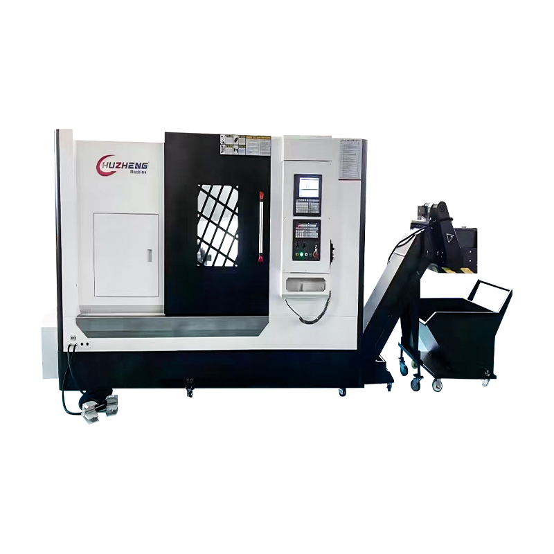
The machine category is known by several names in the industry — 5-axis mill-turn center, turn-mill machining center, multi-axis turning center, and 5-axis multi-tasking machine — all referring to the same fundamental capability: the integration of high-axis-count milling with turning in one platform. Leading machine tool builders offering platforms in this category include DMG Mori (CMX and CTX series), Mazak (Integrex series), Okuma (Multus series), Index, WFL Millturn Technologies, and Hermle, each with distinctive machine architectures that suit different workpiece sizes, production volumes, and industry requirements.
Understanding what each axis in a five-axis mill-turn machine does — and what additional capability each rotary axis adds over a simpler configuration — is essential for evaluating whether a given machine matches a production requirement. Adding axes increases capability but also increases programming complexity, machine cost, and the skill level required to operate the machine effectively. The decision to specify 5-axis rather than 3+2 or 4-axis capability should be justified by the specific part features that require it.
The three linear axes define the Cartesian working envelope of the machine — the physical volume within which the cutting tool can reach any point. X-axis travel governs lateral reach across the machine bed; Z-axis travel determines depth of cut reach along the main spindle axis; Y-axis travel enables off-centerline milling above and below the part centerline. In a mill-turn machine, the Y-axis is particularly important because it is what separates the machine from a simpler CNC lathe with live tooling — without Y-axis travel, off-center features like eccentric bores, parallel key slots, and radially offset drilled holes are either impossible or require creative and inaccurate workarounds using C-axis rotation combined with X-axis positioning.
The B-axis on a five-axis mill-turn machine is a rotary axis that tilts the milling spindle in the X-Z plane — typically through a range of −30° to +210° or similar, depending on the machine design. This tilting capability is the feature that enables true 5-axis simultaneous contouring on a mill-turn platform. With the B-axis, the cutting tool can approach any surface of the workpiece from any angle within the machine's geometric envelope, enabling compound-angle hole drilling, undercut milling, impeller blade machining, turbine vane profiling, and freeform surface contouring that requires the tool axis to continuously change orientation relative to the workpiece surface during the cut. The B-axis also allows the milling spindle to be indexed to the horizontal position for turning operations — the turning tool is effectively held at a precise angle relative to the rotating workpiece spindle, enabling hard turning and thread turning with the milling spindle's powerful drive system.
The C-axis is the rotary axis of the main workpiece turning spindle, programmable as a full CNC positioning and contouring axis rather than simply a continuously rotating drive. For turning operations, the C-axis drives the workpiece at the required spindle speed. For milling and drilling operations, the C-axis indexes the workpiece to any angular position — clocking a cross-hole to a specific angular relationship with a turned flat, positioning a bolt hole circle, or orienting a keyway to a thread datum. In 5-axis simultaneous milling, the C-axis can be used as a coordinated contouring axis together with the B-axis tilt to machine spiral features, barrel cam profiles, and helical flutes on rotating parts — operations that require synchronized motion of both the tool orientation and the workpiece rotation.
Five-axis milling and turning machines are built in several structural configurations that reflect different approaches to achieving the required axis motions, workpiece capacity, rigidity, and accessibility. Each configuration produces different compromises between rigidity, working envelope, chip evacuation, and machine footprint. Understanding these architectural differences helps buyers match a machine platform to the specific part size range and production environment they are planning for.
The most common configuration for medium-to-large five-axis mill-turn centers positions the main workpiece spindle horizontally — like a conventional CNC lathe — with a separate milling spindle mounted on a B-axis swiveling head on the machine column. The turning spindle rotates the workpiece for turning operations while the milling head tilts to perform multi-axis milling. This configuration handles the widest range of shaft and chuck work and benefits from horizontal chip evacuation — chips fall away from the workpiece by gravity, reducing the risk of recutting and thermal damage. Machines in this configuration from Mazak (Integrex i-series), Okuma (Multus B), and DMG Mori (CTX beta TC) are the most widely deployed platforms in precision engineering and aerospace component manufacturing.
Many five-axis mill-turn platforms incorporate a second sub-spindle that picks the part from the main spindle after front-end machining is complete and presents the back face for simultaneous or sequential rear machining. A lower turret provides additional static and driven tooling for simultaneous operations — the upper B-axis milling spindle machines one part feature while the lower turret simultaneously performs turning or drilling on a different diameter. This multi-tool simultaneous cutting capability is what enables the shortest possible cycle times on complex parts and is the configuration standard for high-volume production of complex aerospace and energy components where machine utilization rate and cycle time directly drive unit cost.
For very large workpieces — power generation shafts, large aerospace structural components, oil and gas valve bodies, and wind turbine components — floor-type and gantry five-axis mill-turn machines provide the working envelope and structural rigidity required. WFL Millturn Technologies specializes in this segment, producing machines capable of machining shafts up to 5 meters in length and 1 meter in diameter with full 5-axis milling capability. These machines often include multiple milling spindles, deep-hole drilling units, and in-process gauging systems integrated into the machine structure, enabling complete machining of parts that would require a dedicated machine shop bay and multiple specialized machines in a conventional manufacturing approach.
Five-axis milling and turning machines have become indispensable in industries where part complexity, material difficulty, dimensional accuracy requirements, and the economic pressure to reduce setups all converge. The following sectors account for the majority of five-axis mill-turn machine installations worldwide, and the part types they produce illustrate precisely why the technology is justified over simpler alternatives.
Aerospace is the largest single market for five-axis mill-turn machines. Turbine engine shafts, blisks (bladed disks), impellers, structural fittings, and landing gear components combine turned bearing journals, milled aerodynamic profiles, drilled cooling passages, and compound-angle features in titanium, Inconel, and high-strength aluminum alloys that are difficult to machine and produce expensive scrap when errors occur. A single blisk — an integrally bladed rotor disk that replaces a conventional bladed disk assembly — requires 5-axis simultaneous contouring to machine the complex three-dimensional blade profiles between adjacent blades, combined with turning of the hub bore and rim. Only a five-axis mill-turn machine can complete this component in a manageable number of setups while maintaining the positional tolerances between blade form and hub datum that the engine design requires.
Orthopedic implants, surgical instruments, and dental implant components represent some of the most demanding workpieces in precision manufacturing. Titanium hip and knee implant components combine highly polished spherical bearing surfaces (requiring 5-axis contouring to achieve the geometric accuracy needed for joint function), taper bores and Morse tapers (turned features), and bone-fixation structures (milled undercuts and textured surfaces). Medical grade titanium alloy Ti-6Al-4V is notoriously difficult to machine — it work-hardens rapidly, conducts heat poorly into the chip, and produces built-up edge on cutting tools. Completing a titanium orthopedic implant in one or two setups on a five-axis mill-turn machine rather than four or five setups across multiple machines dramatically reduces the total exposure of the part to handling damage and dimensional creep, and simplifies the traceability documentation required by medical device regulatory standards.
High-pressure valve bodies, choke assemblies, downhole drilling tools, and subsea manifold components in the oil and gas sector are characterized by large, heavy workpieces in corrosion-resistant alloys (duplex stainless, Inconel 625, 17-4PH) with complex internal bore geometries, angled port passages, and precision-lapped seating surfaces. The asymmetric port configurations and angled intersecting bores in these components require B-axis tilt capability for drilling and interpolation milling at compound angles — features that are impossible to achieve without a 5-axis mill-turn capability and would otherwise require custom jigs and multi-setup sequences that introduce unacceptable positioning error in critical sealing surfaces.
Gas turbine compressor wheels, steam turbine blade rings, pump impellers, and generator rotor shafts are produced in low volumes from difficult-to-machine superalloys and large-diameter forgings that represent enormous material value per workpiece. The economic case for five-axis mill-turn machining in this sector is driven by material value rather than volume — a single Inconel 718 turbine disk forging may represent $50,000–$200,000 in material cost before any machining begins. Completing this workpiece in one or two setups on a proven five-axis mill-turn platform eliminates the datum shift risk that occurs when transferring a large, heavy, expensive forging between multiple machines and fixtures, making the machine's premium cost easily justified by the reduction in scrap and rework risk.
Selecting a five-axis milling and turning machine requires evaluating a richer specification set than for either a standalone machining center or a CNC lathe. The specifications interact — a machine with a large turning envelope but limited B-axis range cannot machine compound-angle features, and a machine with excellent simultaneous 5-axis contouring accuracy but inadequate turning spindle torque cannot perform productive roughing of large forgings. The following table covers the critical parameters and what they mean for the machine's practical capability.
| Specification | Typical Range | What It Defines |
|---|---|---|
| Turning Spindle Speed | 2,000–8,000 RPM | Maximum surface speed for finish turning of small diameters and hard materials |
| Turning Spindle Torque | 500–4,000 N·m | Roughing depth of cut and feed capability in hard materials and large forgings |
| Milling Spindle Speed | 8,000–20,000 RPM | Maximum surface speed for milling of aluminum alloys, titanium, and hardened steel |
| Milling Spindle Power | 18–80 kW | Metal removal rate in heavy milling and roughing operations |
| B-Axis Range | −30° to +210° (typical) | Angular reach for compound-angle drilling, undercut milling, and tool approach angle optimization |
| Maximum Turning Diameter | 250–1,500 mm | Maximum workpiece OD that fits within the machine's swing clearance |
| Maximum Turning Length | 500–5,000 mm | Maximum shaft length between spindle face and tailstock |
| Tool Magazine Capacity | 40–320 tools | Number of tools available per program without manual tool changes — critical for long, complex programs |
| Positioning Accuracy | ±2–±5 µm linear | Absolute positional accuracy of the tool tip relative to the workpiece datum |
Thermal compensation is a specification parameter that does not appear prominently in sales literature but has a significant impact on the machine's ability to maintain positioning accuracy during a full production shift. As the machine warms up through spindle rotation, axis drive activity, and cutting heat, the machine structure expands thermally in complex, non-uniform patterns that shift the position of the tool tip relative to the workpiece by several micrometers. High-performance five-axis mill-turn machines include comprehensive thermal compensation systems — using temperature sensors distributed across the machine structure, combined with compensation algorithms built into the CNC control — that continuously correct axis positions to maintain the calibrated accuracy regardless of thermal state. For precision aerospace and medical parts with tolerances tighter than ±10 µm, verifying the effectiveness of the thermal compensation system during a factory acceptance test at full production duty cycle is an essential step before accepting machine delivery.
Programming a five-axis milling and turning machine is significantly more complex than programming either a 3-axis machining center or a CNC lathe independently, and the complexity scales further when simultaneous 5-axis contouring, simultaneous multi-spindle operations, and sub-spindle part transfer sequences are all present in the same program. Effective programming requires both capable CAM software and programmers with deep understanding of the machine's kinematics, toolpath strategies specific to 5-axis mill-turn work, and the collision geometry of the machine in every axis configuration.
CAM systems with mature 5-axis mill-turn capability include Mastercam Mill-Turn, Siemens NX CAM, Hypermill Turn+Mill, SolidCAM iMachining, and Delcam PowerMill (now Autodesk). The quality of the post-processor — the software module that translates CAM toolpaths into machine-specific G-code — is as important as the CAM system itself. A poorly configured post-processor for a 5-axis mill-turn machine can produce code that executes correctly in CAM simulation but causes the machine's CNC to execute the B-axis tilt in a different rotational direction than expected, or fails to handle the kinematic transformation correctly at B-axis positions near the machine's singular configurations (typically at B = 0° and B = 90°). Working with a CAM post-processor supplier that has experience with the specific machine brand and CNC control combination — rather than using a generic post and adapting it — is strongly recommended for shops that are new to 5-axis mill-turn programming.
The complex geometry of a five-axis mill-turn machine — with its B-axis swiveling head, large tool magazine, tailstock, sub-spindle, lower turret, and work envelope that changes with every B-axis and C-axis position — creates collision risk that is essentially impossible to evaluate mentally and highly risky to evaluate by slow-feed prove-out on the machine. Full machine simulation using an accurate virtual machine model — either within the CAM system or in a dedicated machine simulation environment like Vericut or NC Simul — is not optional on five-axis mill-turn programs. It is a mandatory step in the programming workflow. Simulation identifies tool-holder to workpiece collisions, spindle head to fixture collisions, and interference between simultaneously active tool stations before the program runs on real machine time, protecting both the machine and the workpiece from potentially catastrophic collision events that cost days of downtime and significant repair expenditure.
Several toolpath strategies are specific to five-axis mill-turn machining and produce significantly better results than applying standard 3-axis machining center strategies to a mill-turn machine. Barrel cutter (lens-shaped) toolpaths use large-radius cutting edges at a tilted tool angle to machine broad swaths of curved surface in a single pass, dramatically reducing the number of passes needed to machine turbine blade and impeller surface forms while achieving excellent surface finish. Flank milling uses the side of the cutting tool rather than the tip to machine ruled surfaces — this approach produces smooth, accurate surfaces on aerodynamic profiles in a fraction of the time required by point-contact (tip milling) strategies. For turned surfaces machined with the B-axis tilted, the effective rake and clearance angles of the turning insert change with B-axis angle and must be accounted for in the depth of cut and feed rate selection to maintain cutting performance and avoid rubbing.
Workholding on a five-axis mill-turn machine must simultaneously satisfy the clamping requirements for turning — where centrifugal chuck jaw forces at high spindle speeds must maintain secure grip — and the clamping requirements for 5-axis milling, where the fixture must not obstruct the B-axis milling head as it tilts to approach features from multiple directions. This dual requirement produces more demanding fixture design challenges than either a lathe or machining center presents independently.
Low-profile chuck jaws that minimize radial projection above the chuck body are essential for mill-turn work because the B-axis head sweeps through arcs that bring the spindle housing close to the workpiece and chuck. Standard step jaws used on a conventional lathe may cause collision with the milling head during B-axis movement if their height is not assessed against the machine's collision envelope at every B-axis angle used in the program. Soft jaw machining — cutting custom jaw profiles matched to the specific workpiece datum and clamping surface — provides the most precise workpiece registration and allows jaw height to be minimized to exactly what the clamping requirement demands, with no unnecessary material above the clamping surface that could create collision risk.
Long shafts machined on five-axis mill-turn centers require tailstock or steady rest support to control workpiece deflection during heavy roughing cuts — the same requirement as on a conventional lathe. The integration of steady rests and tailstock with the B-axis milling capability requires careful program sequencing: the steady rest and tailstock must be retracted before the B-axis head tilts to access features in their vicinity, then repositioned after the milling operations are complete. Programming the coordination of steady rest positioning with tool movements is a significant part of the setup complexity for long shaft programs on five-axis mill-turn machines, and mistakes in this sequence are among the most common causes of fixture collisions during first-part prove-out. Machines with CNC-controlled steady rests that can be programmed as an additional axis in the part program — rather than requiring manual intervention — handle this challenge most elegantly.
Five-axis milling and turning machines represent a substantial capital investment — typically $500,000 to $3,000,000 or more depending on machine size, configuration, and tooling system — and the decision to invest requires a rigorous business case built on documented production requirements rather than capability aspiration alone. The following factors, when present in combination, build the strongest justification for five-axis mill-turn investment.
Shops that are new to five-axis mill-turn machining consistently underestimate the programming, setup, and operator training time required to realize the machine's full productivity potential. Budgeting for comprehensive factory training from the machine builder, CAM software training specific to mill-turn programming, and a realistic ramp-up period of six to twelve months before the machine reaches steady-state productivity is essential for an accurate ROI projection. The machines that deliver the strongest long-term returns are those where the investment in training and programming capability is treated as inseparable from the hardware investment — not as an optional extra to be deferred once the machine is installed.
Copyright © Xuancheng Huzheng Machinery Trading Co., Ltd. Rights Reserved.


